SPDIF Clock Rate Upgrade for Puffins earlier than S/N 1020
by Shannon Parks 9/23/2020
Background
In August 2020, there was a small Puffin hardware revision which permitted the native rate of 24/96 (24-bits resolution with 96kHz sampling rate) when using the SPDIF mod instead of downsampling to 24/48 (24-bits resolution with 48kHz sampling rate). This downsampling occurred with the original SPDIF mod due to an incompatibility of the main clock frequency and the ARM processor's SPDIF TX interface. This document records the procedure on updating these earlier Puffins to the latest hardware.
This will be a difficult mod for many folks and is only recommended to those who have previously reworked surface mount assemblies. Anyone who repairs modern laptops and phones will be fine.
This mod is not necessary for Analog users as their Puffin operates fully at 24/96. It is only useful for those using a SPDIF output.
If you attempt the mod and it is beyond your capability, I can complete the mod for $99 plus return shipping. I can also do the SPDIF upgrade for you: $99 for the RCA digital coax, or $149 for the Toslink/optical output. I prefer to keep this to US customers only right now, as we are seeing inconsistant and slow international shipping due to the pandemic.
Overview
This mod has five basic steps:
Replacing a clock oscillator
Cutting two PCB traces
Shorting two pins together
Adding one jumper wire
Flashing new firmware
*************************************************************************
A) Replacing a clock oscillator
A1. Add flux to Y1 - the old oscillator which is marked "24.576" - and remove using hot air rework nozzle (6mm diameter or smaller). After removal, clean pads of excess solder and clean flux off area with Qtip and alcohol. Don't use alcohol to excess, as this can drip down to the LCD screen causing discoloration.
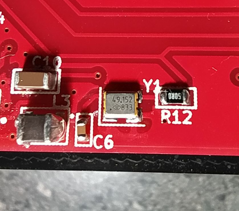
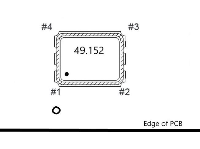
A2. Replace Y1 with new 49.152 MHz oscillator (Digikey part # 1664-1561-1-ND). Note orientation dot on the lower left of the part indicating pin 1. Depending on your Puffin revision, L3, C6, and R12 may have slightly different orientation that the picture below, but the oscillator will be oriented the same. Either reflow with solder paste and hot air, or use the soldering iron method with a fine tip (how I do it). I tin the ground pad and place the part with tweezers. It has to be perfectly centered with the soldering iron method, in order for the fine tip to get adequate pad to solder the pins. Also, watch for solder shorts on the oscillator body (the cutaways). I do this whole process using a 10x inspection scope.
A3. Measure the impedance of the four pins to verify proper soldering. Reference your DMM ground to the input 12V ground lug.
Y1 Pin 1: greater than 5k ohms
Y1 Pin 2: less than 10 ohms
Y1 Pin 3: greater than 5k ohms
Y1 Pin 4: greater than 5k ohms
B) Cutting two PCB traces
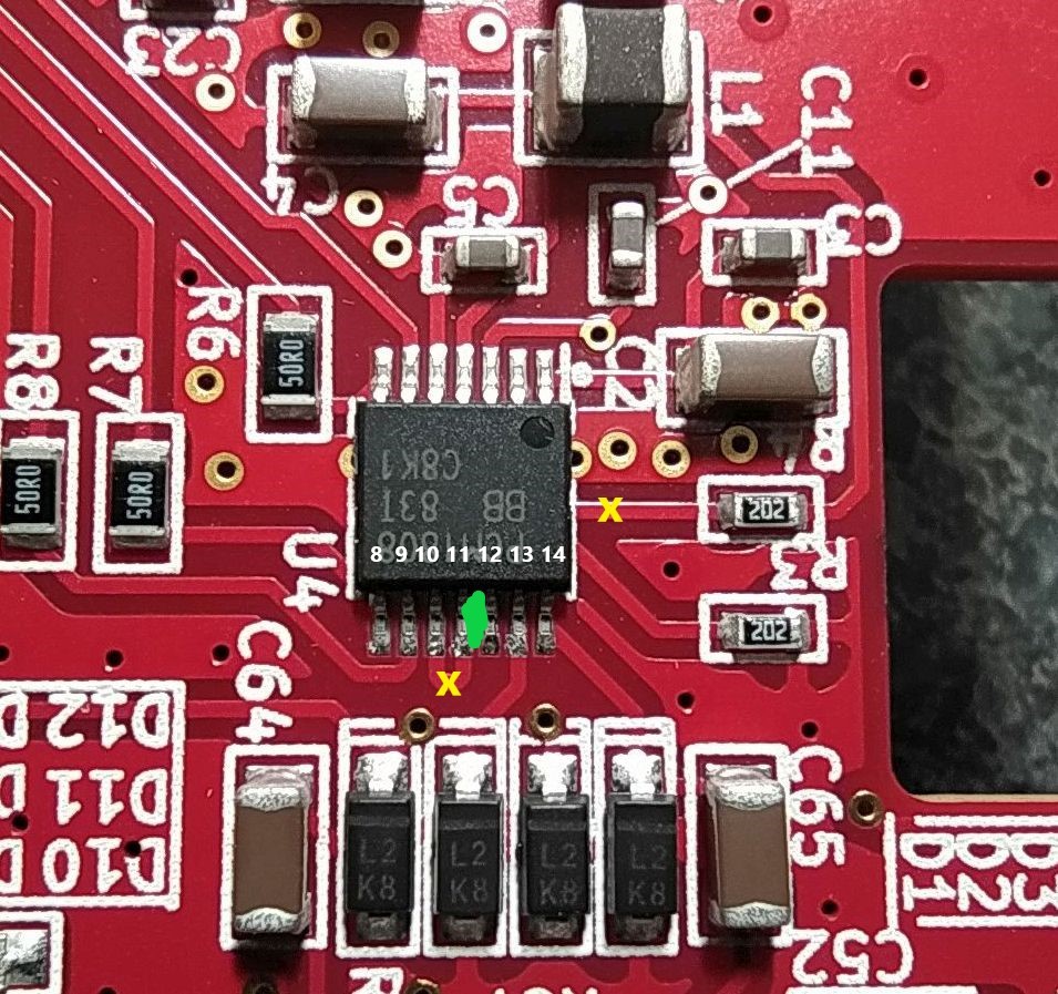
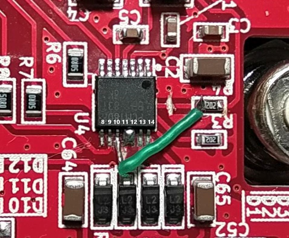
B1. Cut the trace between pins 10 and 11 on U4 (PCM1808). The cut is marked by a yellow 'X'.
B2. Cut the trace between U4 (PCM1808) and R4. The cut is marked by a yellow 'X'. Cut closer to the chip, so that when you solder a wire in step D, you won't short it.

C) Shorting two pins together
C1. Solder together pins 11 and 12. See the green mark on the PCB.
D) Adding one jumper wire
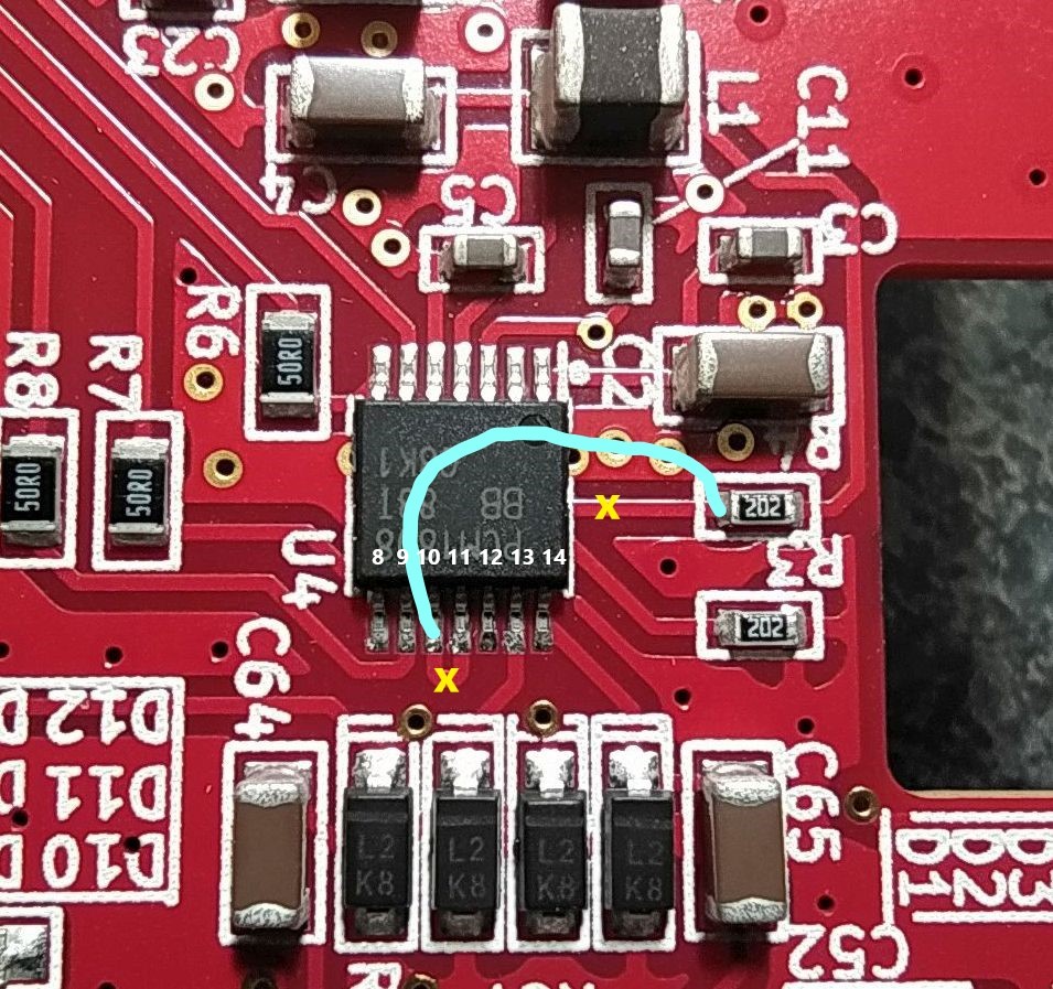
D1. Solder jumper wire from pin 10 to R4 (chip side of component). Run the wire back over the chip like my drawing with the blue line, instead of how I actually did it with the green wire (which is dangerously close to shorting on a nearby diode). On some Puffins there is also an exposed via that can short, too, so do your best to stay out of trouble.
D2. Inspect all reworked areas with with 8x to 10x magnification.
D3. Measure the impedance of the four pins to verify proper soldering. Reference your DMM ground to the input 12V ground lug.
U4 Pin 7: greater than 5k ohms
U4 Pin 8: greater than 5k ohms
U4 Pin 9: greater than 5k ohms
U4 Pin 10: greater than 5k ohms
U4 Pin 11: 2k ohms
U4 Pin 12: 2k ohms
U4 Pin 13: greater than 5k ohms
U4 Pin 14: greater than 5k ohms
E) Flashing new firmware
E1.Download and unzip the latest Puffin firmware: Firmware V1.21 for serial number 1020 and later as well as those 24/96 modified
E2. Follow the firmware update instructions but don't download the older firmware (i.e. skip Step #1): http://www.parksaudiollc.com/firmware.html
E3. 24/96 version of the firmware splashes "version 1.21" at turn on, while 24/48 version of the firmware splashes "ver 1.21" at turn on.