DIY SPDIF Mod Instructions for Parks Audio Puffin Phono DSP
2/28/2021 SP
Overview
The standard Puffin preamp only has analog inputs and outputs. Some users have requested a digital output in order to use their own external DAC. This mod adds an RCA coaxial output with which bypasses the Puffin's internal DAC. For Puffin's at serial number 1020 and higher, this will be a 24-bit 96kHz SPDIF signal. On Puffins earlier than S/N 1020, the Puffin's 96kHz sampling gets downsampled at the SPDIF port to 48kHz due to PLL clock limitations, but all other Puffin processing is done at 96kHz which alleviates any aliasing issues. Information on the more difficult clock upgrade mod for older units (not recommended but documented for posterity) is located HERE.
Summary
This is a pretty easy and straight-forward DIY mod for the Puffin to add a digital RCA coaxial output, suitable for connection to an external DAC. Soldering is required. It adds a new chassis mounted RCA connector to the rear of the Puffin's enclosure. This then connects two wires to a voltage divider made of two axial resistors soldered to the micro board header. Then a special version of the shipping firmware must be flashed to the micro. This new firmware permits switching between Analog and SPDIF outputs (only one output works at a time).
Parts List (Quantity 1 Each Unless Noted)
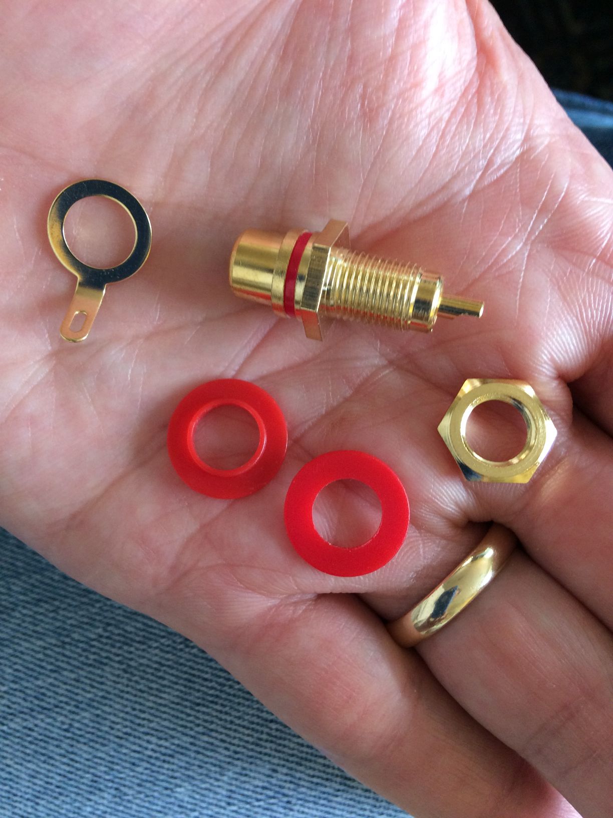
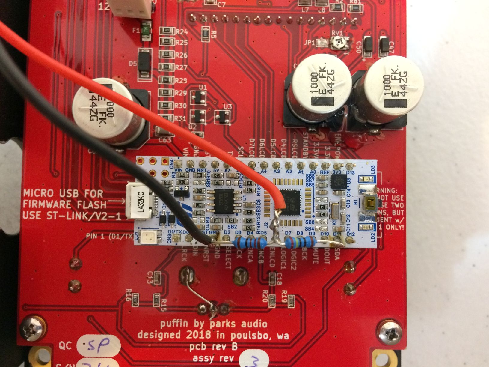
121 ohm 1/2W resistor Mouser MF0207FTE52-121R --can sub with +/-5% similar value resistor1) Add isolated RCA chassis connector.
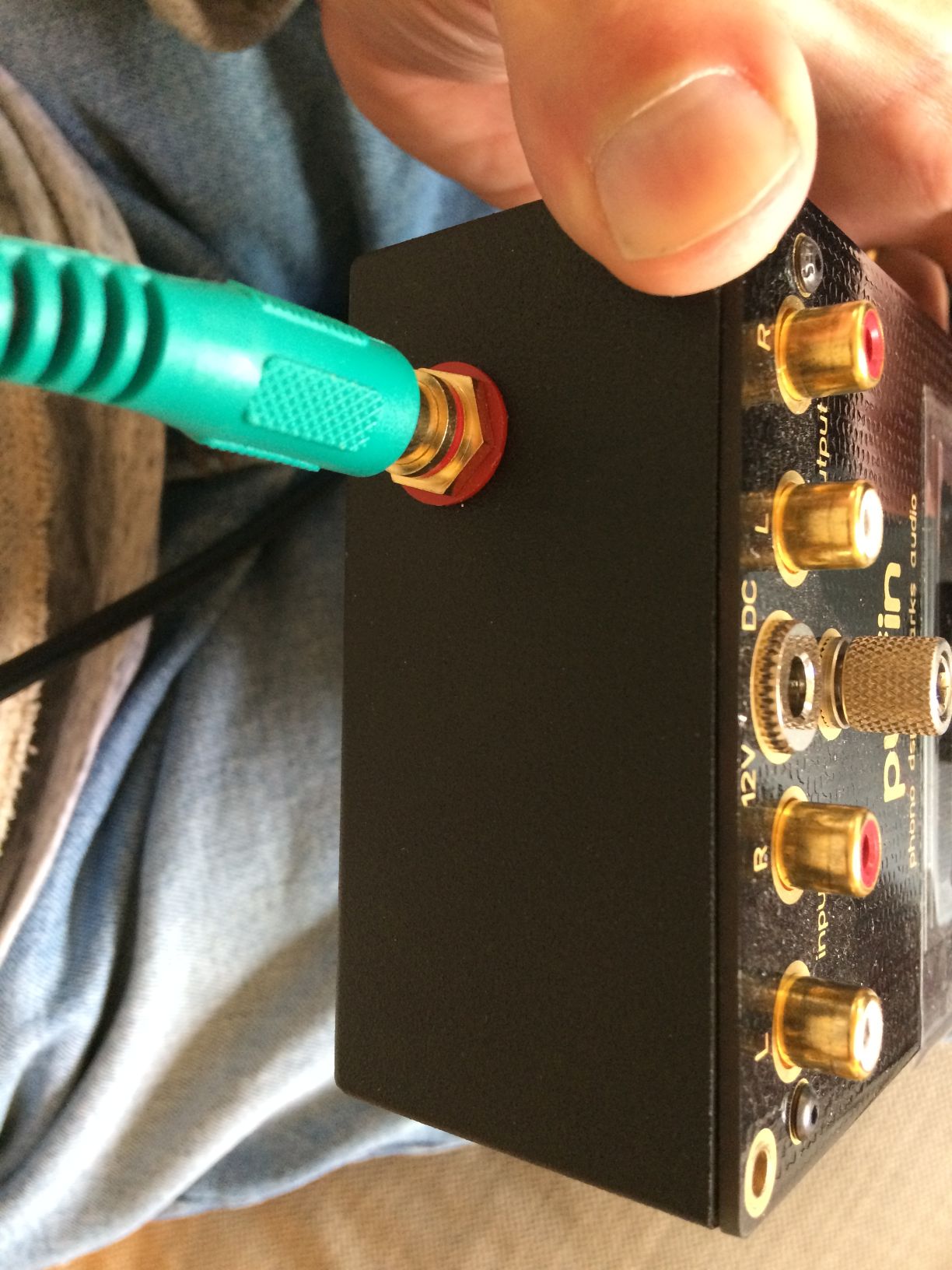
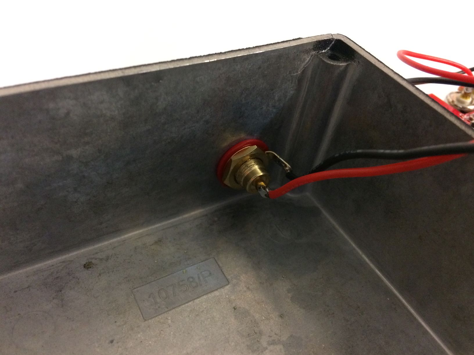
Drill a 3/8" (10mm) hole in the rear Puffin chassis (7/8" (22mm) from side of chassis, 5/8" (16mm) from bottom of chassis). You'll want to use a chassis RCA connector with the insulating washers. To drill this hole, I use a drill press with a Unibit #1 and lock the chassis in place. Use Loctite to prevent RCA nut from loosening over time. Put it in as follows:RCA female connector//plastic washer with rib//Puffin chassis wall//plastic washer flat//ground ring (bend solder leg)//nut//RCA solder center solder cup
2) Solder wires to RCA connector.
Strip 1/4" (6mm) from ends of the 8" wires and presolder (tin) the exposed wire to ease soldering. Solder 8" black wire to RCA ground ring. Presolder RCA center solder cup, and then solder 8" red wire to center RCA cup.
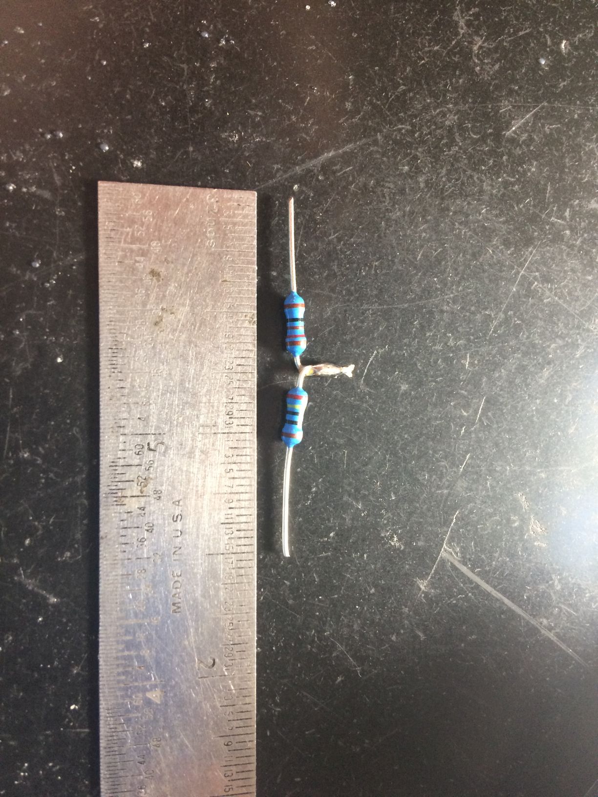
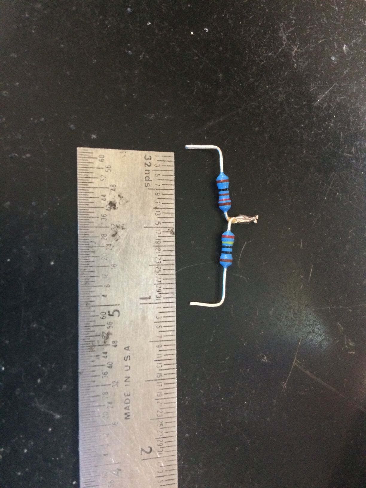
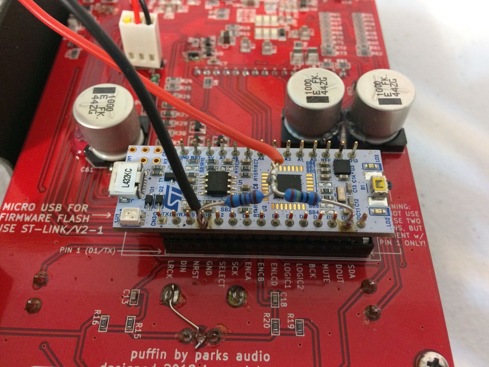
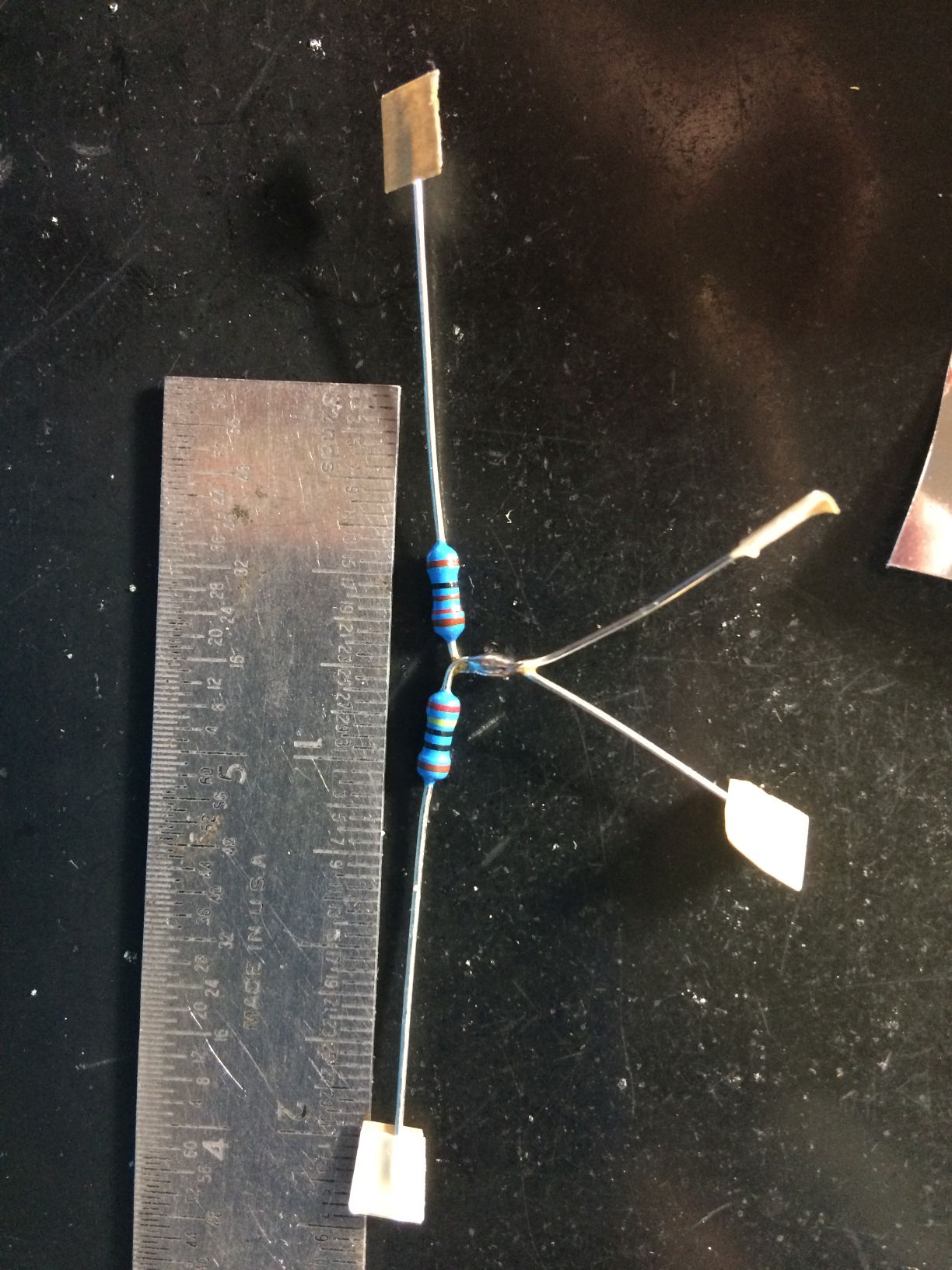
3) Form a voltage divider with resistors and solder to micro header.
Solder the two resistors as shown. The legs will be around 1" apart which is the distance we need to neatly solder to the micro header. Presolder the two ends. Presolder micro header pins marked D11 and GND (same side as D11). Orientation is important: make sure the resistor with the yellow band (240 ohms) is solderd to D11 and the other resistor goes to GND. Solder the resistor voltage divider to the micro header. Double-check that you don't create any shorts to other pins. After it has cooled a minute, bend the center nub of this divider parallel with the micro board. Basically we don't want it to short out on the bottom of the chassis.
4) Solder wires to voltage divider.
Solder the other end of the black wire to the GND pin junction. Solder the other end of the red wire to the resistor junction. Since these wires are pre-tinned, you shouldn't need to add any more solder. Once again, double-check that you don't create any shorts to other pins.
5) Flash firmware to latest firmware.
Update to latest firmware if you haven't already. In the Puffin menu, use Out to change to SPDIF from Analog mode. You can switch it from Analog to SPDIF and back again on the fly.